Laser cutting equipment (6)
(4) Integrated cutting equipment
In the integrated cutting device, the laser is mounted on the frame and moved longitudinally in the frame, and the torch is integrated with the driving mechanism to move laterally on the frame beam, and the various molding parts can be cut by the numerical control method. In order to compensate for the lateral movement of the torch to change the length of the optical path, it is usually provided with an adjustment of the optical path length, which can obtain a homogeneous beam within the cutting area and maintain the homogeneity of the quality of the cutting surface.
The integrated cutting device generally uses a high-power laser, which is suitable for the cutting process of large-size steel structural parts of medium and heavy plates (8-35mm). Table 5 lists the processing capabilities of the integrated laser cutting equipment. The main technical parameters of LMX integrated laser cutting equipment are shown in Table 6.
Table 5 Processing capacity of integrated laser cutting equipment
Laser power / kW | 1.4 | 2 | 3 | 6 |
Effective cutting range / mm | 1830×7000 | 2440×36000 | 4200~36000 | 2600~36000 |
Cutting carbon steel maximum thickness / mm | 9 | 16 | 19 | 40 |
Table 6 Main technical parameters of LMX integrated laser cutting equipment
model | LMX25 | LMX30 | LMX35 | LMX40 |
Effective cutting width / mm | 2600 | 3100 | 3600 | 4100 |
Effective cutting length / mm | According to user requirements (standard 6m) | |||
Gauge / mm | Effective cutting width +1700 | |||
Total track length / mm | Effective cutting width +4800 | |||
Cutting machine height / mm | 2200 | |||
Torch height floating stroke / mm | 200 | |||
Drive mode | Rack and pinion driven on both sides | |||
Cutting feed rate / mm · min -1 | 6 to 5000 | |||
Rapid feed rate / mm·min -1 | 24000 | |||
Cutting torch up and down movement speed / mm · min -1 | 1200 | |||
Origin return accuracy / mm | ±0.1 | |||
Positioning accuracy / mm | ±0.0001 | |||
Laser (CO2 gas laser) | TF3500 (rated power 3kW) or TF2500 (rated power 2kW) | |||
(5) Laser cutting robot
The laser cutting robot has a CO 2 gas laser and a YAG solid laser cutting robot. Laser cutting robots are usually used for both cutting and welding.
1) CO 2 laser cutting robot
A schematic diagram of the structure of the L-1000 CO 2 laser cutting robot is shown in Figure 11.
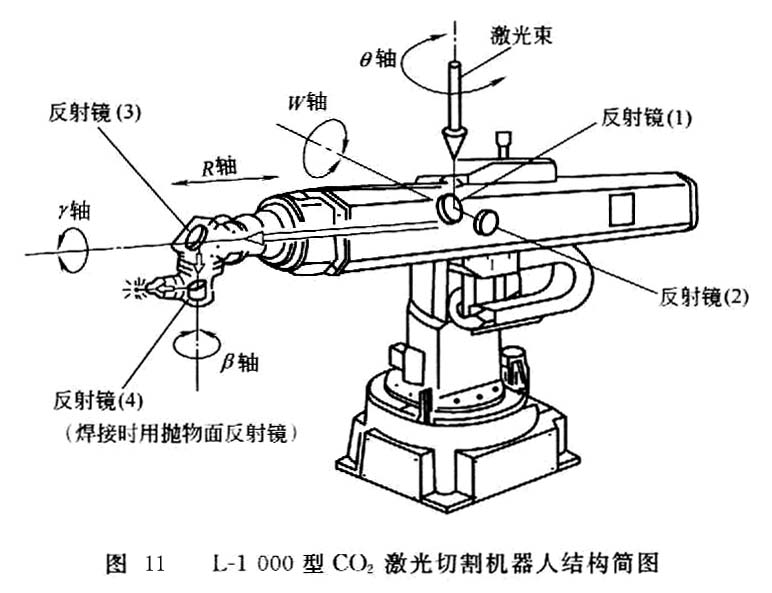
The L-1000 CO 2 laser cutting robot is a polar coordinate 5-axis control robot equipped with a C1000 to C3000 laser. The light beam is transmitted through four mirrors disposed in the robot arm, and is focused and then ejected from the nozzle. The mirror is made of copper, and the surface is subjected to reflection treatment so that the beam transmission loss does not exceed 0.8%, and the positional accuracy of the focus is quite good. In order to prevent the mirror from being stained, the optical path is completely out of contact with the outside, and the cleaned air filtered by the filter is also filled in the optical path and has a certain pressure to prevent the surrounding dust from entering.
The main technical parameters of the L-1000 CO 2 laser cutting robot are shown in Table 7.
Table 7 Main technical parameters of L-1000 CO 2 laser cutting robot
project | Technical Parameters | |
Action form | Polar coordinate | |
Control axis number | 5 axes (θ, w, R, γ, β) | |
Setting status | Fixed to the ground or suspended on the gantry | |
The scope of work | θ axis / (°) | 200 |
w axis / (°) | 60 | |
R axis / mm | 1200 | |
γ axis / (°) | 360 | |
轴 axis / (°) | 280 | |
Maximum speed | θ axis / (°) · s -1 | 90 |
w axis / (°) · s -1 | 70 | |
R axis / mm · s -1 | 90 | |
γ axis / (°) · s - | 360 | |
轴 axis / (°) · s - | 360 | |
The front part of the arm can carry the mass / kg | 5 | |
Drive mode | AC servo motor servo drive | |
control method | Digital servo control | |
Position repeatability / mm | ±0.5 | |
Number of laser mirrors | 4 | |
Laser inlet diameter / mm | 62 | |
Auxiliary gas piping system | 2 sets | |
Optical path cleaning air piping system | 1 set | |
Laser mirror cooling water system | 1 set of inlet and outlet | |
Mass of mechanical structure part / kg | 580 | |
2) YAG solid laser cutting robot
The structure of the multi-joint YAG laser cutting robot developed in Japan is shown in Fig. 12.
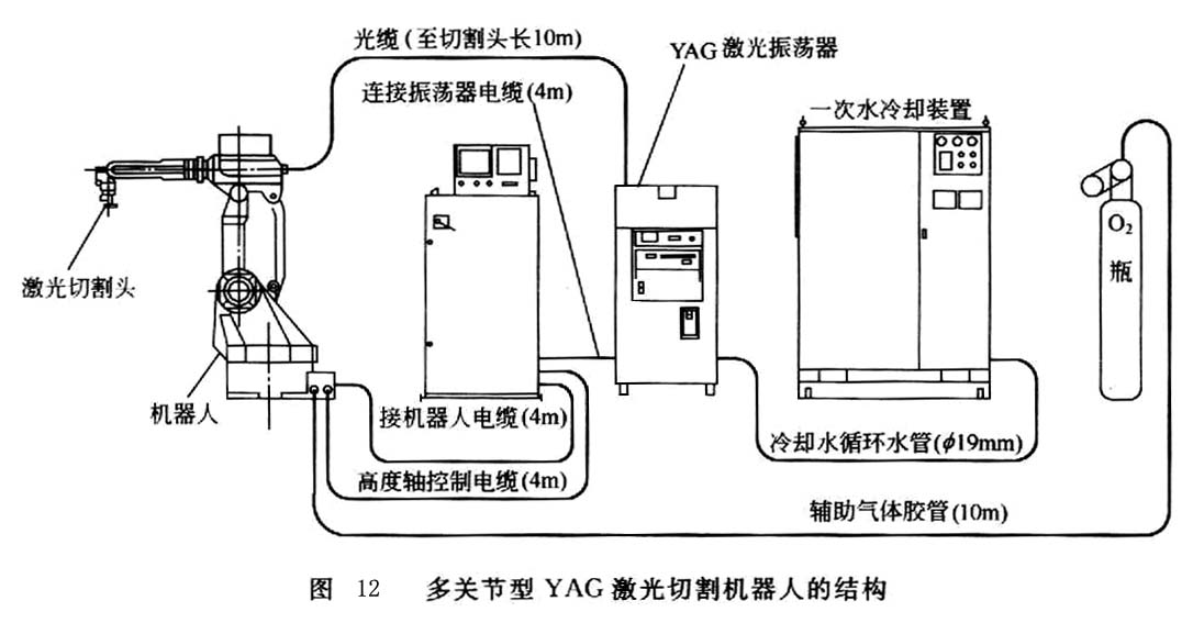
The multi-joint YAG laser cutting robot uses optical fibers to directly transmit the beam from the laser to the torch mounted on the robot arm, so it is more flexible than the CO2 gas laser cutting robot. This kind of robot is made up of the original welding robot. It adopts the teaching method and is suitable for the trimming, punching and cutting of three-dimensional metal parts such as car body moldings.
Previous page