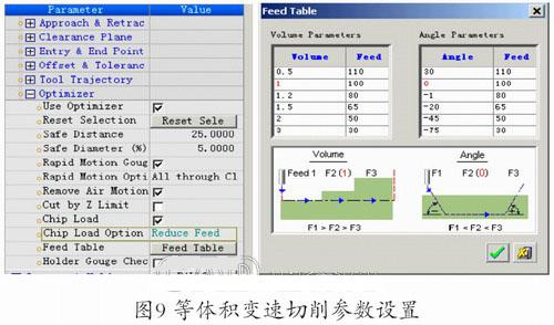
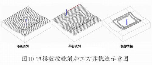
I. Introduction C imatron software is a CAD/CAM/PDM product from Cimatron of Israel. It is a system that realizes full-featured 3D CAD/CAM on a microcomputer platform earlier. The system provides a flexible user interface with excellent 3D modeling, engineering drawings and comprehensive CNC machining capabilities, as well as a variety of general purpose, dedicated data interfaces and integrated product data management capabilities. Since its entry into the market in the 1980s, Cimatron has been popular in the international mold manufacturing industry, covering users in the fields of machinery, railways, research, and education. Cimatron E is a newer version that provides solutions for product manufacturing, mold design, and tooling manufacturing to streamline manufacturing cycles. Its rich data exchange interface can directly import and export data to UG/Parasolid, Pro/ENGINEER, and CATIA, and can exchange data formats such as IGES, Step, STL, DXF, DWG, and SAT. The system provides parameterized hybrid digital modeling of two-dimensional graphics output, part assembly, standard mold base and other functional modules, and can be modeled for surface, without physical conversion. Its powerful surface function facilitates the design of various molds, especially for injection mold design. The system provides a fast electrode design and Mould Design injection mold design that automates the assembly and assembly of the product, the split mold and the standard mold frame. Cimatron E provides intelligent 2~5 axis CNC machining programming and supports high-speed NURBS program output. Cimatron E supports CNC milling, turning, and wire cutting programming. The five-axis CNC milling process includes five-axis bottom edge, side edge, five-axis curve and drilling programming, based on residual blank machining and CNC programming template for cutting programming, based on variable speed and high speed machining. The Cimatron E SDK provides a rich library of functions based on Visual C++ and Visual Basic secondary development languages. In the Microsoft VisualStudio integrated development environment, these function libraries can be used to easily develop their own dedicated applications, providing a better platform for the expansion of system function modules. Second, the product mold design The parting design in the plastic forming process of injection molding, forging, casting and other products is the most important part of the mold design. With the help of the parting application provided by the Cimatron E system, the user can quickly complete the parting line. , Separation of the parting surface, parting simulation and other functions. Good parting design directly affects the CNC machining of the subsequent product and the mold, the injection molding simulation and the final forming of the product. Cimatron E system's parting design has draft analysis, shrinkage design, parting line design, parting surface design, parting surface seam compensation, convex and concave mold blank loading, mold coordinate system definition, mold parting and simulation, convex and concave mold output And other design features. Figure 1 shows a product and mold parting surface made with Cimatron E. Third, the injection mold design guide With the mold mold design expert system Mold Design provided by Cimatron E system, users can complete the complete mold design, including parting design, standard mold base, standard and non-standard design assembly, electrode design and other functions, and in 3D or 2D drawing data output. The mold design guide mainly includes the following main contents: loading convex and concave mold, cooling, injection, ejection mechanism, positioning design, standard mold base and standard parts call, non-standard part design and sub-assembly design, engineering drawing and BOM output, NC CNC machining code design, etc. MoldDesign is a solution based on 3D parametric solid modeling. It automates the 3D design of the mold. It can complete the design and loading assembly of all individual parts, component parts and standard parts. It can easily divide the model into cores and cavities. , sliders and inserts. Cimatron E's Mold Design module for injection mold design allows users to design the following functions: (1) loading the convex and concave mold working parts on the movable mold base; (2) positioning the convex and concave mold working parts; (3) standard formwork call; (4) loading replacement mold working components, such as screws, injection ejection mechanism units, sliding units, etc.; (5) Cooling and injection flow channel design; (6) BOM output; (7) mold design rules and configuration storage; (8) One-mode multi-cavity design. Mold Design mold design module standard mold frame call, BOM output and mold design standard template configuration call and other functions, so that users can rationally configure the enterprise's own resources, while improving the efficiency and quality of mold design. Figure 2 shows the standard mold base and standard parts call product interface provided by the system; Figure 3, Figure 4, and Figure 5 are the design examples of the convex and concave mold of a certain product, the mold design and assembly tree, and the zero components after the mold design is completed. BOM table. Fourth, the electrode design In the mold cavity manufacturing process, the slits, sharp corners or roots that cannot be finished by metal cutting can be electrically processed, so the electrode design must be performed. As a key part of EDM, the rationality of the electrode design affects the formation of features such as slits, sharp corners or roots, profiles, and the selection of electrical parameters that affect processing efficiency. Using the electrode design module provided by CimatronE, users can complete complete electrode design and electrode engineering output, automate electrode design, manufacturing, process image information management, accelerate electrode analysis, extraction, generation and documentation. The electrode design flow is to define the spark machining surface, the three-dimensional information of the electrode extracted according to the working surface, the electrode blank setting (the blank is generally provided with a circle and a square), the electrode coordinate system setting, the electrode holder design, the electrode peripheral contour creation, and the lap joint. Extended surface design, etc. The system provides the spark surface and electrode body discharge gap setting, new electrode design and engineering drawing output. On the basis of the formed electrode, the standard electrode can be stored in the form of template, and the user can complete the electrode design of multi-cavity or similar features. In addition, the system can also perform vivid visual simulations such as electrode simulation processing. Figure 6 shows a dedicated electrode designed for rectangular slits in the product cavity. Cimatron E numerical control programming consists of three important parts: 3D modeling, tool path design, tool path editing and modification, machining simulation, post processing, NC programming template, secondary development function interface, data file exchange and so on. The system provides point machining programming functions such as drilling, tapping and boring cycles. It has a variety of contour machining, contour cutting and cutting and island machining plane milling programming. It provides 3~5 coordinate complex surface multi-axis linkage machining programming function, with multiple tool path control based on residual blank, surface contour, contour stratification, surround equidistance, curved streamline, corner clearing, curve five axes, etc. the way. The main machining strategies for tool path include parallel milling, wrapping, contouring, deep hole drilling, roughing based on various forms such as blanks. Cimatron E provides mold milling machining programming that is simple and convenient, and absorbs the advantages of CNC programming functions of other CAD/CAM systems. System-rich three-axis rough machining combined with intelligent cutting based on residual blanks, control of high-speed cutting trajectory, coarse-finishing of forward rake and roll angle of 5-axis controlled tool axis vector, rapid drilling, and roughing With the programming function, the CNC machining program of the product can be completed quickly and efficiently. For each machining strategy, there are many control methods for tool path generation. For the machining of large-volume pockets and space surfaces, the tool path is controlled by: Stock Spiral based on residual blanks; Parallel cut of space surface, its trajectory is parallel to a straight line on the XY plane; a point on the plane is the center of the circle, and the trajectory is radially processed in the radial direction (Radial); contour layer milling (By Layer) ); 3D Step of the surface contour; 3D Step; the contour of the trajectory along the contour of the surface is fixed in the XY plane of the Z-axis. Profile; deep hole drilling roughing displacement (Plunge Mill ); space curve triaxial or five-axis machining (Curve 3x & Curve 5x). The typical tool path control strategy is shown in Figure 7. 1. Cimatron E CNC programming basic process Since the system interface is designed strictly according to the CNC machining process of the actual product, its operation is simple. During the entire tool path design and planning process, the machining object, cutting parameters and other contents can be arbitrarily modified. It is worth noting that due to its correlation, When designing a tool path, it is best to have a general plan for the definition of the machined object. It can copy, paste, delete and hide the tool path and machining program. At the same time, it can edit and modify the specific tool path plan, such as the following knife and corner speed adjustment. The system NC machining programming module provides the following functions: Observing the movement of the tool along the trajectory in the graphical mode, and performing graphical modification; having the function of copying, editing, modifying, tool definition, machine tool and cutting parameter database of the tool position file, such as The tool path is extended, shortened, trimmed, and so on. Cimatron E is used for CNC machining of product parts. The flow is shown in Figure 8. The first is to call the product part to load the blank, call the system template or user-defined template, design the tool. Then, the machining program, the definition operation, the machining object, and the machining method are respectively created to generate the corresponding machining program. The user establishes the tool path generation method according to the content of the machining program. For example, according to the specific content of the machining object, the tool guiding mode, cutting step distance, spindle rotation speed, feed amount, cutting angle, advance and retreat cutting point, interference surface and safety The tool path is generated by details such as plane. After the tool path is simulated and processed, the corresponding editing, copying and copying operations are performed to improve the programming efficiency. After all the tool path design is qualified, post-processing is performed to generate the machining code of the corresponding CNC system for DNC transmission and CNC machining. 2. Mold NC programming template The use of CNC programming templates facilitates the use of existing experience and expert knowledge to achieve the purpose of sharing resources within the enterprise. The system provides the machining program template, tool template, machining object template, tool path template and so on. In the template, the knowledge, experience and habits of CNC programmers, processing technicians and skilled workers are continuously injected, and the standardized CNC machining process is established, which lays a good technological foundation for strengthening the production management and improving the processing efficiency and quality of the products. Cimatron E system creates user's own template to set the pre-processing sequence, process parameters and cutting parameters. For similar parts processing objects, applying templates can greatly improve the efficiency and quality of CNC programming, especially in the mold industry. Users can easily obtain expert-level manufacturing process guidance from templates through the machining wizard. The entire content can be easily and effectively provided to inexperienced users, which is beneficial to absorbing other people's experience. Through the wizard, pre-defined templates can be activated and quickly generate CNC machining tool tracks with simple interaction. The machining program template and the tool path template are saved in file formats of *.pct, *.tpt, and *.mtt, respectively. 3. Variable speed cutting and based on residual blank cutting The Cimatron E system provides the same volume constant-speed variable-speed cutting function, which is especially suitable for the cutting of difficult-to-machine materials with large machining allowances on ordinary CNC machine tools, so as to give full play to the performance of tools and machine tools. Since the proportion of ordinary CNC machine tools in existing enterprises is still large, the tool path strategy using variable speed cutting can reduce the manufacturing cost and improve the processing efficiency. Figure 9 shows the variable speed cutting function settings provided by the system. CimatronE's high-speed milling capabilities support contoured roughing and surface finishing, avoiding 90 by rounding corners at corners. Sharp turn (high-speed occasions are easy to damage the guide rail and motor), and adopt the screw advance and retract knife with the automatic adjustment function of the feed speed, which is very suitable for high-speed cutting. The system also provides various methods such as surround equidistance to support high-speed machining tool path. Generate a strategy. With the programming function based on residual blank cutting, the software automatically eliminates empty tool paths, reducing the user's workload and improving programming efficiency. As shown in Fig. 10, on the CimatronE platform, the tool path of the hot stamping die cavity and the core CNC milling program of a composite product product is fully utilized by the system numerical control programming template and the equal volume variable cutting function. Sixth, the conclusion Cimatron E is a very versatile CAD/CAM integration software that is ideal for the development and processing of a wide range of molds. This article is only the most basic applications. I believe that with the familiarity and application of Cimatron E, we will find more and more powerful functions. I hope this article can play a role in inspiring. And the product parting design, injection molding cavity core design, mold frame loading and convex and concave die CNC three-axis milling programming programming of some key technologies, the content is comprehensive and comprehensive, the examples are from the actual production, the article has a higher reference value. 


Five, Cimatron E mold CNC milling programming 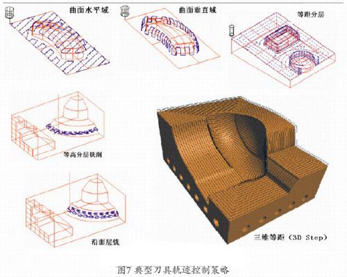

In the article, the author describes in detail the use of Cimatron E for injection mold design and CNC machining programming.