Application of Pro/E animation design module in product development process (Figure)
In today's product development process, it is common to improve engineering design efficiency through collaborative work. The communication of information is also becoming more and more important. Prior to the advent of 3D design software, engineering drawings contained all the data information for the entire product, and because of its important role, it was also called engineering language. As the pace of product upgrades and updates continues to accelerate, the structure of the product itself is increasingly complex, and the engineering drawings alone cannot express the designer's overall intention. When the parameterized core Pro/ENGINEER provides the 3D solid design function, it is quickly accepted by the majority of users. Design Animation can demonstrate the real-life situation of the product in a dynamic form in the Pro/ENGINEER assembly. Even if the communication partner does not have a CAD workstation, it can still be transmitted through the MPG or JPG output from the Animation. Enriched the content and methods of information exchange.
Yada Electronics is a backbone company of the world-renowned Emerson Group, and its main product power series has been at the leading level in the industry. The company has been using Pro/ENGINEER software as the only 3D design tool for 4 years. The company has maintained good relationships with customer suppliers (including PTC) and has conducted regular engineering information exchange activities as an important part of product development.
Second, the general process of making animation
Although Animation is to be operated in an assembly, it does not require all the 3D solid features of all parts to be completed, because the detailed features of 3D entities are often in the stage of product design. And the completion of Animation before this is a better choice.
Once the main part is built into the initial simple 3D model, you can animate it. When the 3D entity changes and changes, the correlation of Pro/ENGINEER itself will be automatically mapped to the assembly. At this time, the Animation will be regenerated, which will enable the Animation to react to the latest status of the product. It is not recommended to create an animation using a source assembly that contains the original skeleton model. You can make a separate assembly file based on the focus of the animation. Because the assembly relationships in the source assembly are fully defined at the same time as the part is built, some animation effects need to be defined in the assembly to different constraints than the source assembly. Of course, the final position of the part in the new assembly file must match the source assembly. Let's take a model of Yada Company as an example to introduce the production process of Pro/ENGINEER 2001 animation design.
This model is a high-power power supply. The main components consist of a face-shell heatsink, a bottom case, two fan assemblies, a PCB assembly and a power outlet. As shown in Figure 1. The fan assembly and PCB assembly contain different parts. The assembly relationship is that the fan assembly is mounted on the cover heat sink, the PCB assembly and the power socket are mounted in the bottom case, and the bottom case is finally fixed on the face case. Each component is fixed by a screw connection.

Figure 1 All parts in the original position
The animation we expect to receive includes information on the assembly process of the complete machine and the working state of the simulated fan, as well as the general shape characteristics of the main part. These are the concerns of suppliers, production departments and customers. Obviously, the engineering drawing cannot express this information, and the physical assembly file does not have the dynamic dynamic kinetic energy of the animation. The first part to be loaded in the assembly is the face shell heatsink, which needs to be fully defined with the three reference faces of the assembly file, and then loaded into other subassemblies and parts. Since the movement state of the fan is to be output, the assembly connection of the blades needs to be specially treated in order to define the servo motor.
Once the total assembly is complete, you can begin dragging each component or part to the desired location and taking a snapshot save for animation. When you drag a part, the system defines the part as a different default body based on the assembly relationship, and the system drags the part to implement the dragging of the part. You can drag all subjects except Ground. If the default body defined is different from the expected value, it needs to be redefined.
Ground in this example is the first part of the shell heatsink, as shown in Figure 2. Dragging a body is similar to modifying the exploded state in an assembly. However, there are a lot of function options here, in addition to the usual translation, you can move or rotate at will. With the addition of restrictions, you can also drag a part to a relatively specific position on another part.
During the dragging process, the system checks if this step conflicts with the original defined assembly relationship and issues a warning message depending on the situation. After dragging to the expected location, you can take a snapshot and save it. The default snapshot of the system is called snapshot “nâ€.
Repeat the above operation: define the body (do not need to define it each time) → drag the part → take a snapshot, just like the process of breaking the product apart.

Figure 2 Status after dragging parts
Snapshots can borrow locations from each other, but there is no parent-child relationship. For the actual assembly order reflected by the final animation effect, consistency between snapshots is required. The ideal state should be like a person going up the stairs, starting with the bottom layer and gradually reaching the top layer, capturing a snapshot for each step.
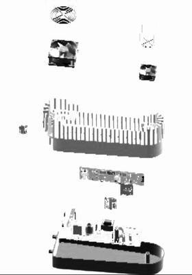
Figure 3 The state of all parts dragged to the final position
Once you have accessed the required snapshot, you can edit it into a movie clip. The video clip is a presentation of N snapshots that appear in sequence over time, and is a core component of the animation. The completed movie segment will automatically appear in the timeline below the main Pro/ENGINEER window. Then define the servo motor of the fan, the system will also put it into the timeline, and then you can run this animation. In order to make the animation vivid, the different display modes of the angle of view and the part are usually added to the timeline, and then the whole editing is performed. After the editing is completed, the presentation effect can be played, and if there is any uncoordinated condition, the modification is performed until the best is achieved. Program.
Third, the outlook
As a visual tool for conveying design intent, Animation can express the intuitive and detailed 3D entities and the assembly relationship between them more clearly, which is very convenient for users. It mainly focuses on the reproduction of the real state of the product in the virtual environment. If the virtual environment has strong industry specificity, the content of this module will be more abundant.
Smart Ceiling Fan,Intelligence Ceiling Fan,Five Blades Ceiling Fan,5 Blades Ceiling Fan
Jiangmen MagicPower Electrical Appliances Co.,Ltd. , https://www.mpceilingfan.com