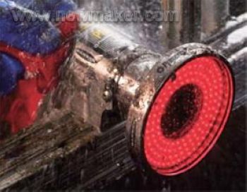
Process sensing of the workpiece Process monitoring of workpieces is researched and applied earlier and more than process monitoring techniques for tools and machine tools. Most of them target the quality control of workpiece processing. Since the 1980s, workpiece identification and workpiece mounting pose monitoring requirements have also been mentioned on the agenda. Roughly speaking, the process identification is a process for identifying whether the executed machining process is a machining requirement of the workpiece (zero); the workpiece identification is to identify whether the workpiece to be processed into the machine tool or the blank is a workpiece or blank to be processed, and also It is required to identify whether the pose of the workpiece installation meets the requirements of the process specification. In addition, workpiece identification and workpiece mounting monitoring can be used to sense the machining allowance and surface defects of the blank or workpiece to be machined. Completing these identification and monitoring will employ or develop many sensors, such as TV or CCD based machine vision sensors, laser surface roughness sensing systems, and the like. Figure 4 shows the ColorSight_9000 series of color sensors from AB in the United States. It has a self-learning function that actively recognizes the color of the workpiece. The color sensor is mainly used to identify the color, that is, to determine whether the detected color of the workpiece is consistent with the desired color. The color sensor can roughly know the chromaticity of the measured color, etc., but is not used to measure the absolute value of the chromaticity like the spectroscope. The structure of the color sensor mainly includes a photodiode and a color filter. The working principle is that the measured color is decomposed into RGB values ​​by a color filter, and then the intensity of each color is separately detected by a photodiode. Because color sensors have color recognition capabilities, device manufacturers can apply them to a wide variety of applications, including the mechanical manufacturing industry. As long as it is a color-related industry, you can consider using a color sensor. For equipment vendors, this also means they have more opportunities. As long as it is used properly, it is possible to produce incredible products. Even with the vision of a device manufacturer, color sensors can be the key to product differentiation. Figure 4. Color sensor for machine tool processing In addition to the color sensor, the visual sensor is one of the more applications, and Figure 5 shows the vision sensor in the machining application. Figure 5, the visual sensor at work In principle, a vision sensor has thousands of pixels that capture light from a single image. The clarity and detail of the image is usually measured in resolution, expressed in pixels, such as part of the vision provided by Banner Engineering. The sensor is capable of capturing 1.3 million pixels. Therefore, the sensor can “see†a very delicate target image no matter how many meters or centimeters away from the target. After capturing the image, the vision sensor compares it to the reference image stored in memory for analysis. For example, if the vision sensor is set to identify a machine component that is correctly inserted with eight bolts, the sensor knows that the component with only seven bolts, or the component with the bolt misalignment, should be rejected. Furthermore, the visual sensor can make a determination no matter where the machine component is located in the field of view, whether or not the component is rotated within 360 degrees. In mechanical manufacturing, complex vision systems are a mature technology that performs detailed automated inspections. Vision sensors give machine designers greater flexibility than photoelectric sensors. In the past, applications requiring multiple photosensors can now be tested with a single visual sensor. Vision sensors are able to inspect much larger areas and achieve better target position and directional flexibility in machine manufacturing, making vision sensors popular in some applications that previously relied on photosensors. Traditionally, these applications also require expensive accessories and precise motion control that ensures that the target object always appears in the same position and posture. Tool or grinding wheel sensing The cutting and grinding process is an important material removal process. The tool and the grinding wheel are worn to a certain limit (determined by the blunt standard) or damaged (damage, chipping, burn, plastic deformation or the general name of the reel), so that they lose the cutting ability or the machining accuracy and the finished surface are not guaranteed. When it is sex, it is called tool/grinding wheel failure. According to industry statistics, tool failure is the primary cause of machine downtime, and the downtime caused by it accounts for 1/5 to 1/3 of the total downtime of NC machine tools. In addition, it can cause equipment or personal safety incidents, even major accidents. Taking a tool sensor and its application system as an example, the load on the tool during the cutting process is related to many factors. According to the requirements of the online test, only a few large influencing factors are considered, namely the spindle speed, the feed speed, and the cutting. The tool life and wear level can be measured by the tool load model by various factors such as depth and cutting performance of the machined material. The present invention provides a multifunctional pull faucet, comprising: a faucet body, a drawing part is provided at the water outlet port thereof, and the drawing part is connected to a main channel, wherein at least three are provided in the faucet body A branch channel, and the three branch channels are all connected to the main channel. A multifunctional pull faucet provided by the present invention, wherein the hot water channel, the cold water channel and the water purification channel (pure water channel) are all connected to the main channel , And the main channel is connected with the drawing part on the main body of the faucet, so that the drawing part can obtain the water quality (hot water, cold water, purified water or pure water) required by different users, thereby improving the user experience, and , By integrating the hot water channel, cold water channel and pure water channel (pure water channel) into the main channel, the internal structure of the faucet is simplified, and the production cost of the faucet is reduced. Pull Out Faucets,Pull Out Kitchen Tap,Pull Out Sink Faucet,Standard Pull Out Faucet Yuyao Zelin Sanitary Ware Co., Ltd , https://www.kitchen-sinkfaucet.com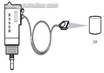
Previous page 1 2 Next page